Seu Carrinho
Não existem mais produtos no seu carrinho


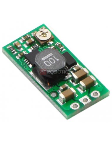


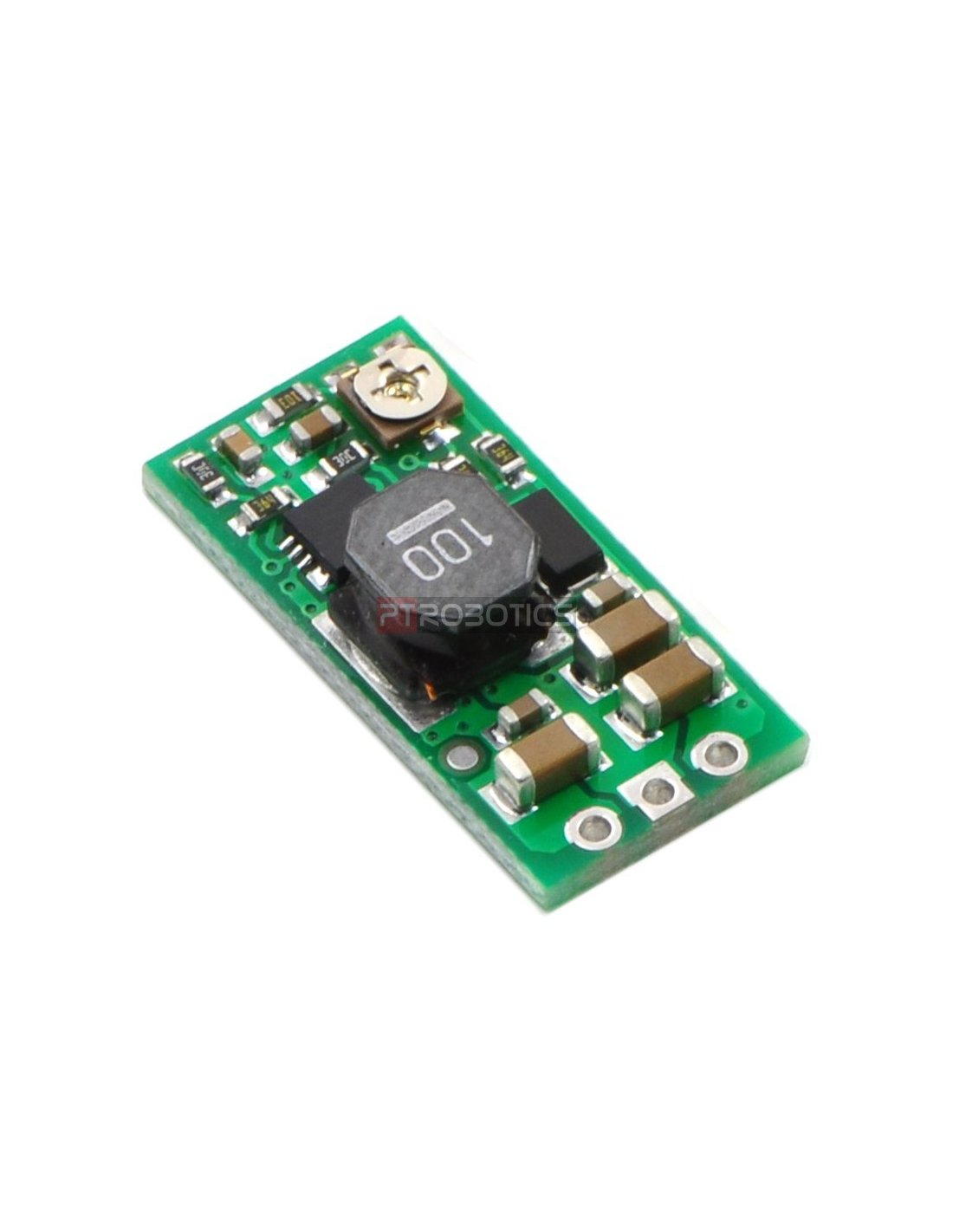
Regulador de Tensão Ajustável 2.5-9.5V
Informação do fabricante:
The Pololu adjustable boost regulator is a very flexible switching regulator (also called a switched-mode power supply, SMPS, or DC-to-DC converter) that can generate voltages higher than its input voltage. We offer two adjustable ranges: approximately 2.5 V to 9.5 V and 4 V to 25 V. The output voltage can be set using the trimmer potentiometer in the upper-right corner of the board. The input voltage range is 1.5 V to 16 V (the input voltage should be kept below the output voltage). The integrated 2 A switch allows for output currents high enough to drive small motors, as in our 3pi robot, and allows large voltage gains, such as obtaining 24 V from two NiMH or NiCd cells.
Some example applications include:
Feature summary
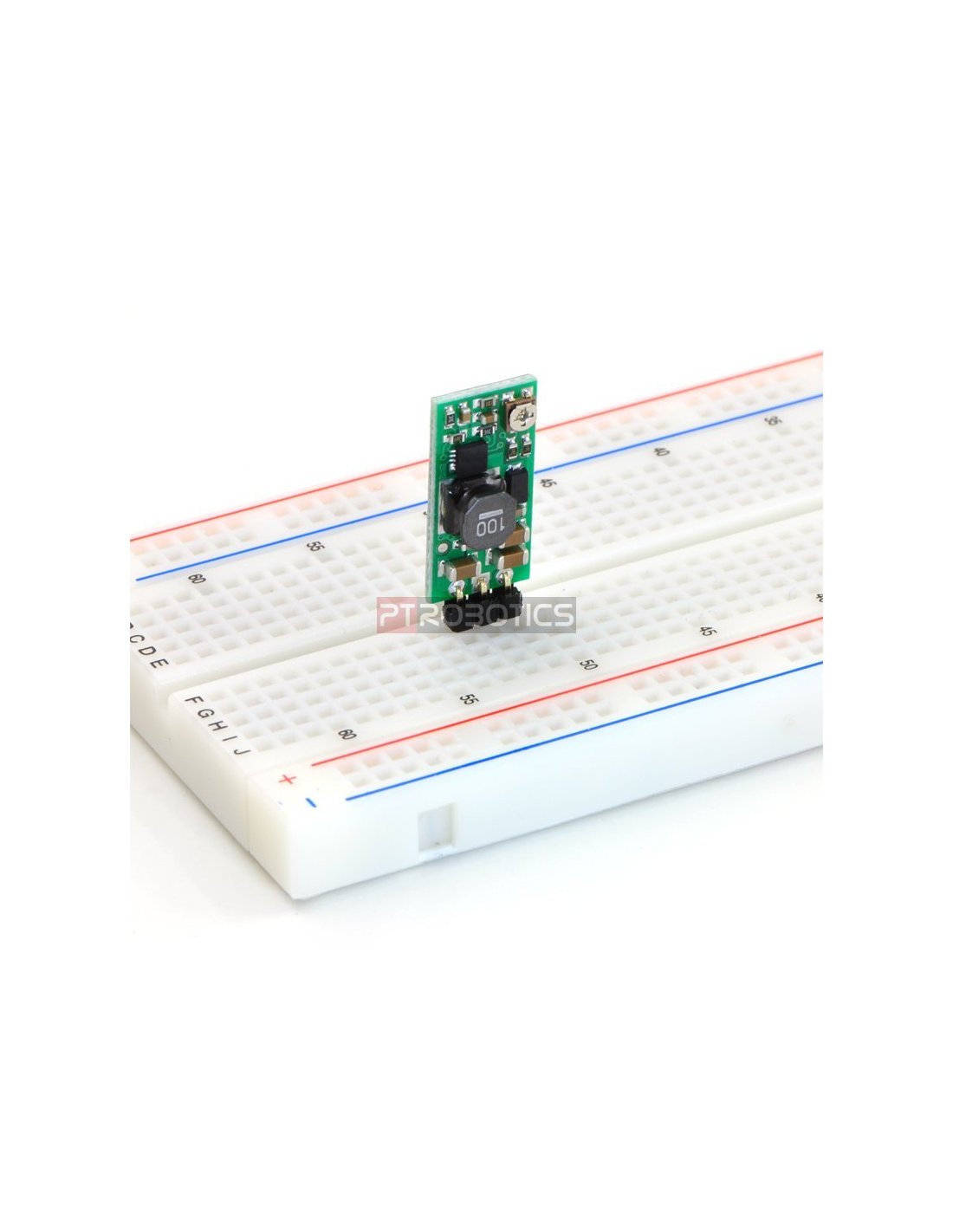
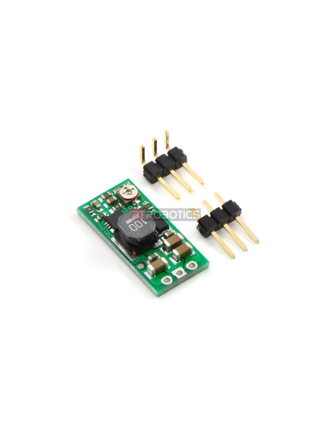
Connections
The boost regulator has just three connections: the input voltage, ground, and the output voltage. These three connections are labeled on the back side of the PCB, and they are arranged with a 0.1″ spacing along the edge of the board for compatibility with standard solderless breadboards and perfboards and connectors that use a 0.1″ grid. You can solder wires directly to the board or solder in either the 3×1 straight male header strip or the 3×1 right-angle male header strip that is included.
Setting the output voltage
The output voltage can be adjusted using a meter and a light load (e.g. a 10 kΩ resistor). Turning the potentiometer clockwise increases the output voltage. The output voltage can be affected by a screwdriver touching the potentiometer, so the output measurement should be done with nothing touching the potentiometer.
Warning: You should be careful not to use an input voltage that exceeds the output voltage setting, so we recommend setting the output voltage with the input voltage around or below 2.5 V (e.g. using one or two alkaline batteries). Note that the potentiometer has no physical end stops, which means that the wiper can be turned 360 degrees and into an invalid region in which the output voltage is set to approximately 2.5 V (for both the 2.5 V to 9.5 V and 4 V to 25 V versions).


