Seu Carrinho
Não existem mais produtos no seu carrinho


Este Kit contém um disco magnético e sensores de Hall effect
Add quadrature encoders to the mini plastic gearmotors on your Romi chassis with this kit that uses a magnetic disc and Hall effect sensors to provide 12 counts per revolution of the motor shaft. The sensors operate from 3.5 V to 18 V and provide digital outputs that can be connected directly to a microcontroller or other digital circuit.
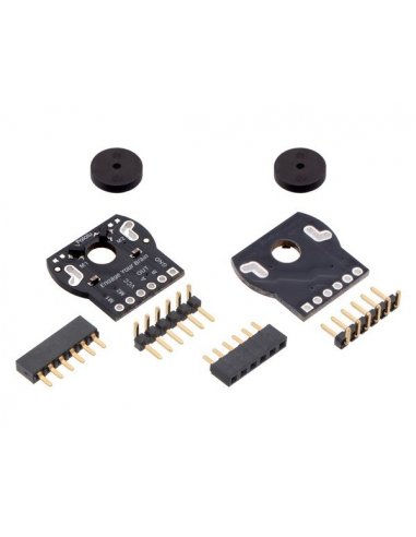
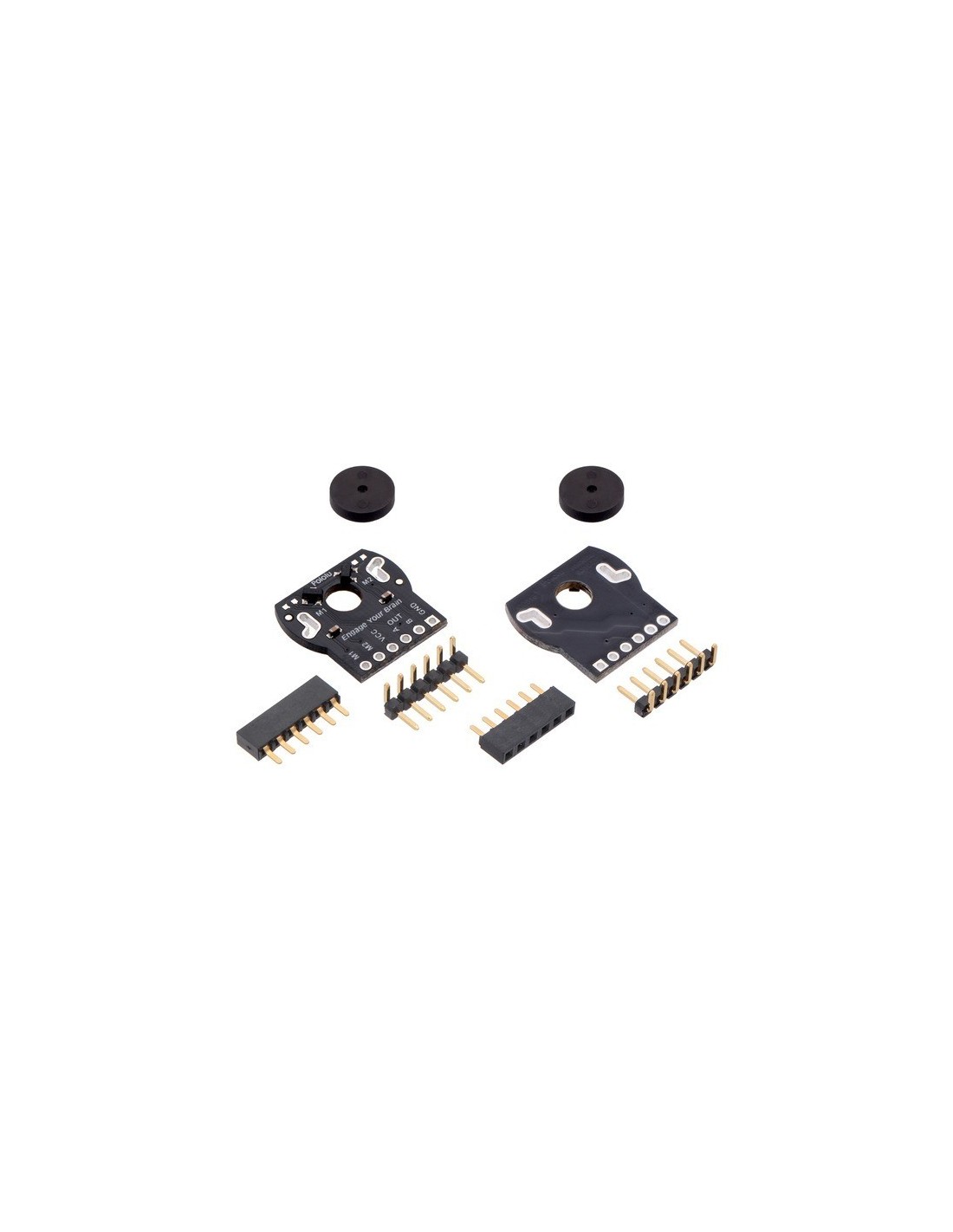
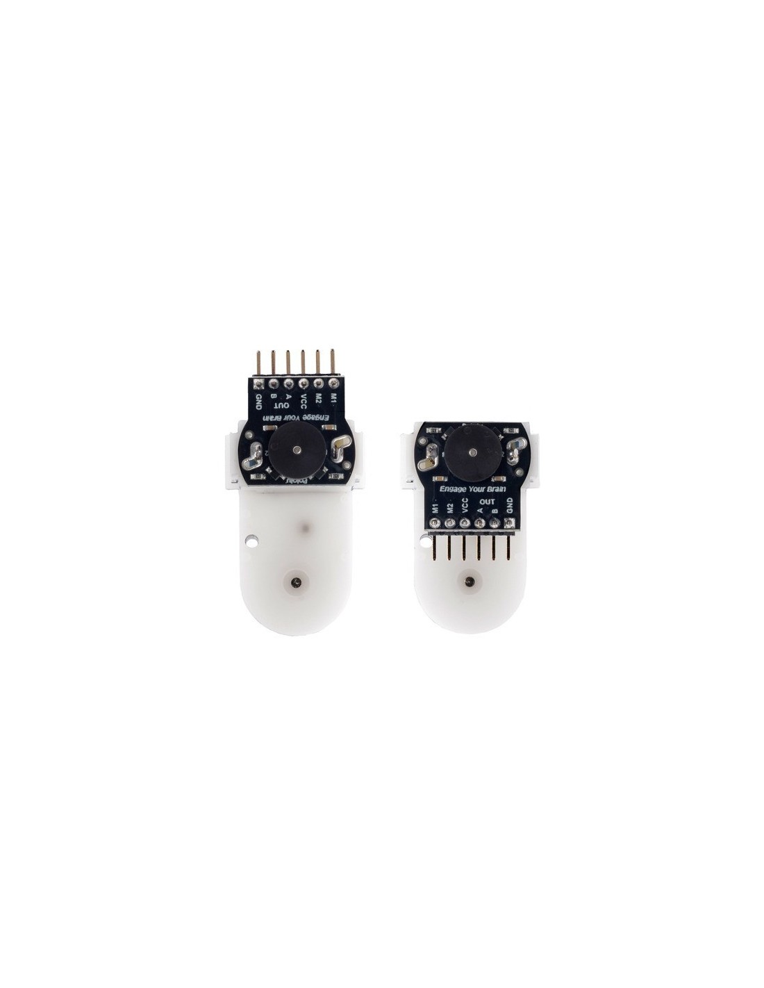
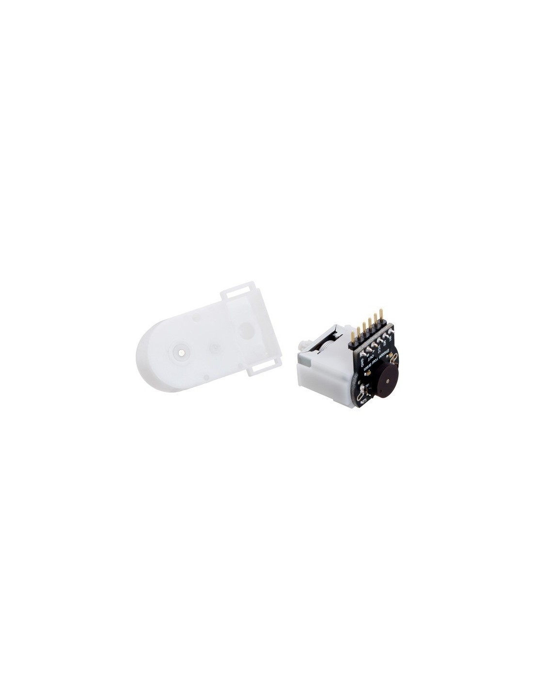
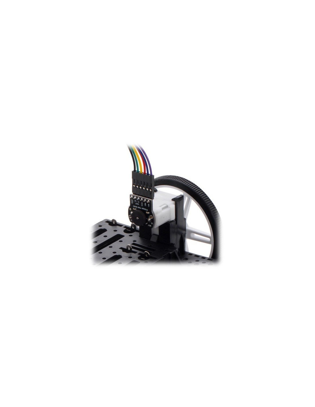
his kit includes two dual-channel Hall effect sensor boards and two 6-pole magnetic discs that can be used to add quadrature encoding to the mini plastic gearmotors on a Romi chassis. The encoder board senses the rotation of the magnetic disc and provides a resolution of 12 counts per revolution of the motor shaft when counting both edges of both channels, which corresponds to approximately 1440 counts per revolution of the Romi’s wheels.
This compact encoder solution fits within the 11.5 mm × 22.5 mm cross section of the rear of the motors on three of the four sides. The fourth side of the encoder has the signal and power connections, and it extends 7 mm past the edge of the motor so that it is at just the right height to be able to plug into a board mounted below on the Romi chassis when the included low-profile male and female header pins are used. The assembly does not extend past the end of the extended motor shaft, which protrudes 5 mm beyond the back of the motor.
The encoder board is designed to be soldered directly to the back of the motor, with the back shaft of the motor protruding through the hole in the middle of the circuit board. One way to achieve good alignment between the board and the motor is to tack down the board to one motor pin and to solder the other pin only when the board is flat and well aligned. Be careful to avoid prolonged heating of the motor pins, which could deform the motor case or brushes.
Tradução em Português brevemente disponível!


