Seu Carrinho
Não existem mais produtos no seu carrinho


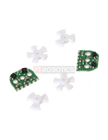


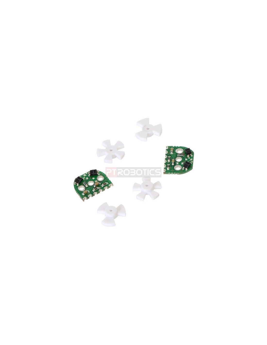
Add quadrature encoders to your micro metal gearmotors (extended back shaft version required) with this kit consisting of two sensor boards, two 3-tooth encoder wheels, and two 5-tooth encoder wheels.
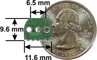
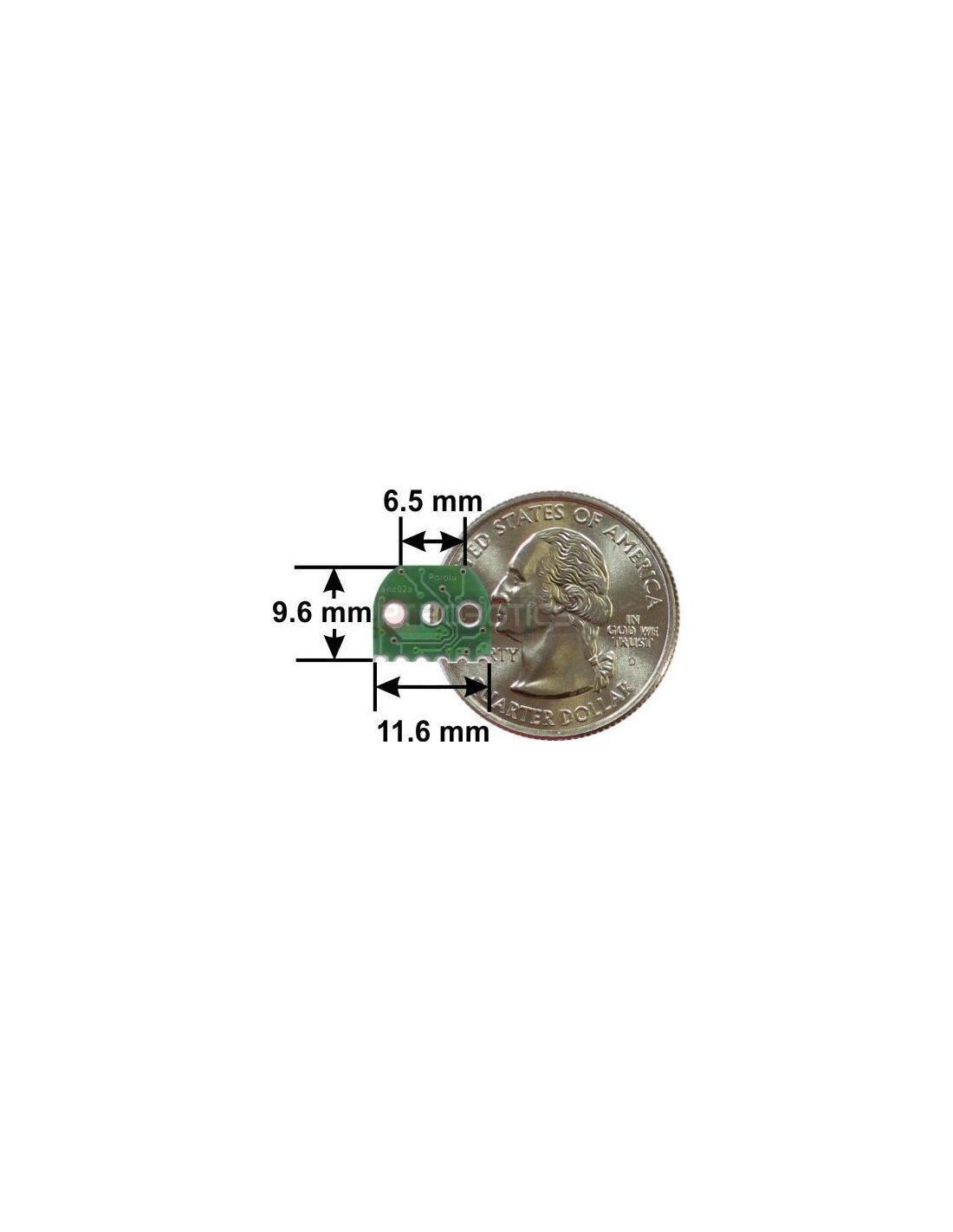
Add quadrature encoders to your micro metal gearmotors (extended back shaft version required) with this kit consisting of two sensor boards, two 3-tooth encoder wheels, and two 5-tooth encoder wheels. The installed system does not exceed the 12 mm × 10 mm cross section of the motors and extends only 5 mm beyond the plastic motor end cap. The 3-tooth wheel provides 12 counts per revolution; using the 5-tooth wheel yields 20 counts per revolution. This version is intended for use at 5 V.
This set includes sensor boards and reflective wheels to add quadrature encoding to two micro metal gearmotors with extended back shafts. 3-tooth and 5-tooth encoder wheels are included to provide options of 12 counts per revolution and 20 counts per revolution of the motor shaft (to compute the encoder counts per revolution of the gearbox output, multiply by the gear ratio). Because the encoder board outputs are direct phototransistor outputs, some signal conditioning is often necessary between the sensor and a digital system processing the signals.
Note: This sensor system is intended for relatively advanced users comfortable with the physical encoder installation and with using the resulting signals. It only works with micro metal gearmotors that have extended back shafts.


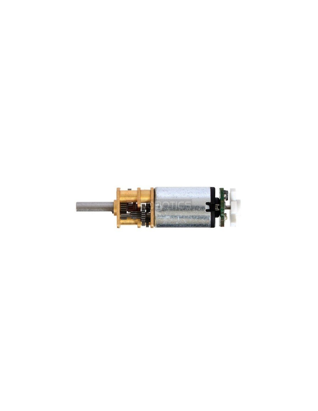
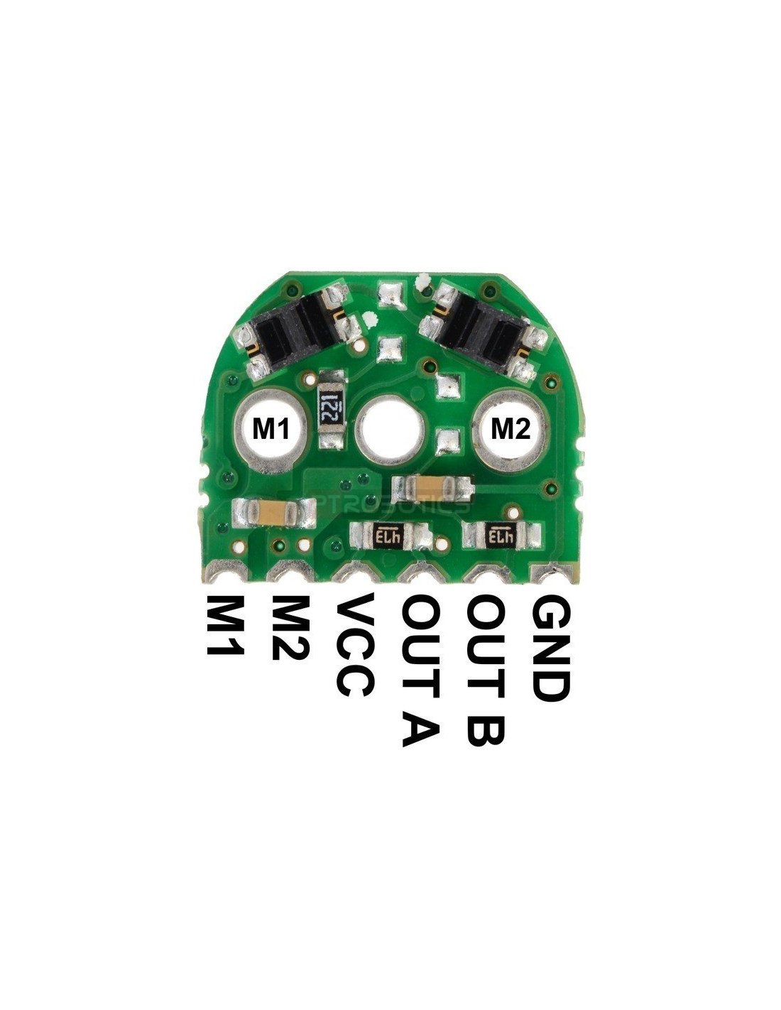
the encoder board is designed to be soldered directly to the back of the motor, with the back shaft of the motor protruding through the hole in the middle of the circuit board. the better aligned the board, the better the output signal quality will be. one way to achieve good alignment is to tack down the board to one motor pin and to solder the other pin only when the board is well aligned. be careful to avoid prolonged heating of the motor pins, which could deform the plastic end cap of the motor or the motor brushes. once the board is soldered down to the two terminals, the motor leads are connected to the m1 and m2 pads along the edge of the board, along with the power for the sensors and the two quadrature outputs:
Pinout and Installation

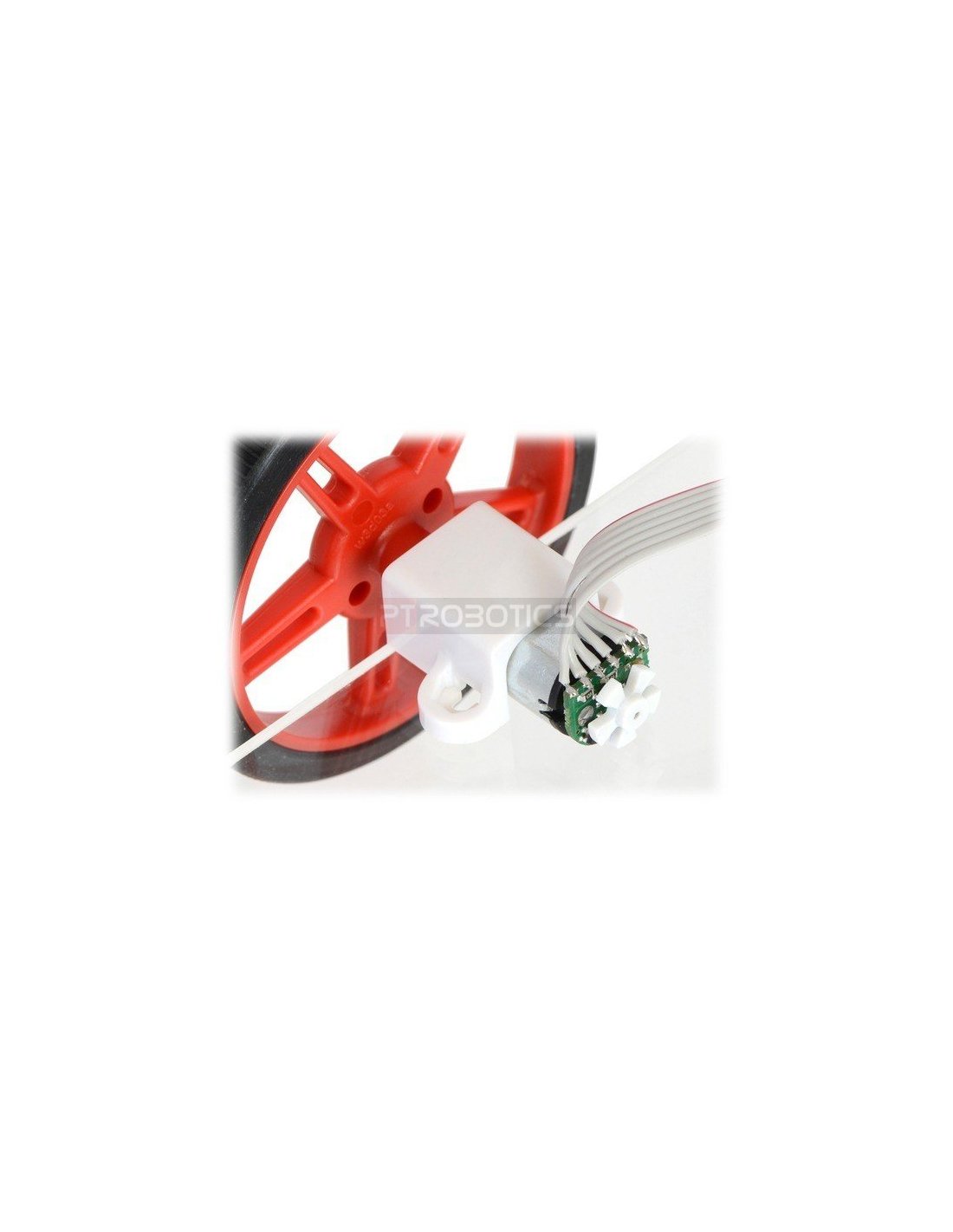
The edge connections are on a 2 mm pitch. The board can be soldered perpendicularly to another PCB, to a 2 mm connector, or to individual wires as show here:
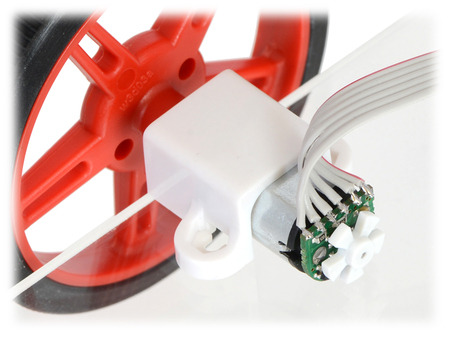
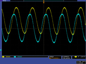
Once the board is soldered to the motor, the plastic encoder wheel can be pushed onto the motor shaft. The encoder wheel should be pushed on far enough that the gap between the wheel and sensors is approximately 0.5 mm. One way to get consistent gaps is to use a few sheets of paper or a business card as a shim when installing the encoder wheel. The best way to confirm optimal placement of the encoder wheel is to look at the signal with an oscilloscope. The following sequence of screen captures show the output for a 5-tooth wheel spinning at approximately 30,000 RPM as the wheel is pushed closer and closer to the sensors. Example of an installed micro metal gearmotor reflective optical encoder.
5V encoder version, motor approx. 30k RPM: 5-tooth wheel way too far from sensors.
5V encoder version, motor approx. 30k RPM: 5-tooth wheel slightly too far from sensors.

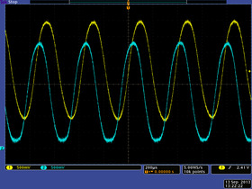
5V encoder version, motor approx. 30k RPM: 5-tooth wheel at optimal distance from sensors.
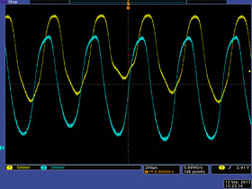
5V encoder version, motor approx. 30k RPM: 5-tooth wheel slightly too close to sensors.

5V encoder version, motor approx. 30k RPM: 5-tooth wheel way too close to sensors.
The center oscilloscope capture above shows what the signal outputs look like with the wheel mounted at an optimal distance from the sensors. Note that even in this optimal case, the signals from the two channels are different due to inherent variations in the two reflectance sensors, but both signals are 90° out of phase and both span a large voltage range.
With the appropriate signal conditioning (e.g. comparators with hysteresis), all of the outputs, except perhaps for the last case, would still yield reliable position counts. The outputs also tend to improve at lower speeds and with the 3-tooth wheel.
The encoder boards are available in two versions that are optimized for operation at 5.0 V and 3.3 V. The only difference is in the electrical configuration of the IR LEDs in the reflectance sensors:
 |
The 5 V version with LEDs in series draws approximately 12 mA; the 3.3 V version with LEDs in parallel draws approximately 24 mA.
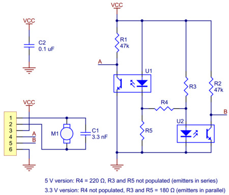 |
| Schematic diagram for the micro metal gearmotor reflective optical encoder. |
|---|
This schematic is also available as a downloadable pdf (145k pdf).


