Seu Carrinho
Não existem mais produtos no seu carrinho


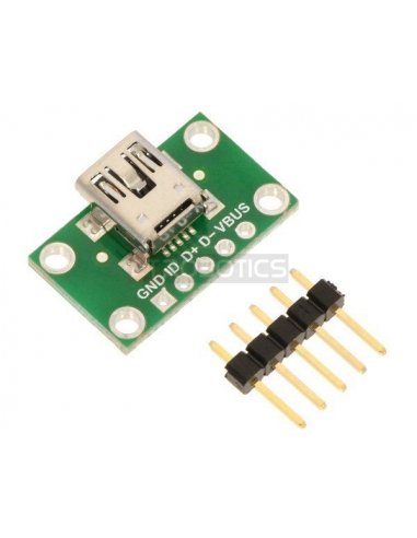


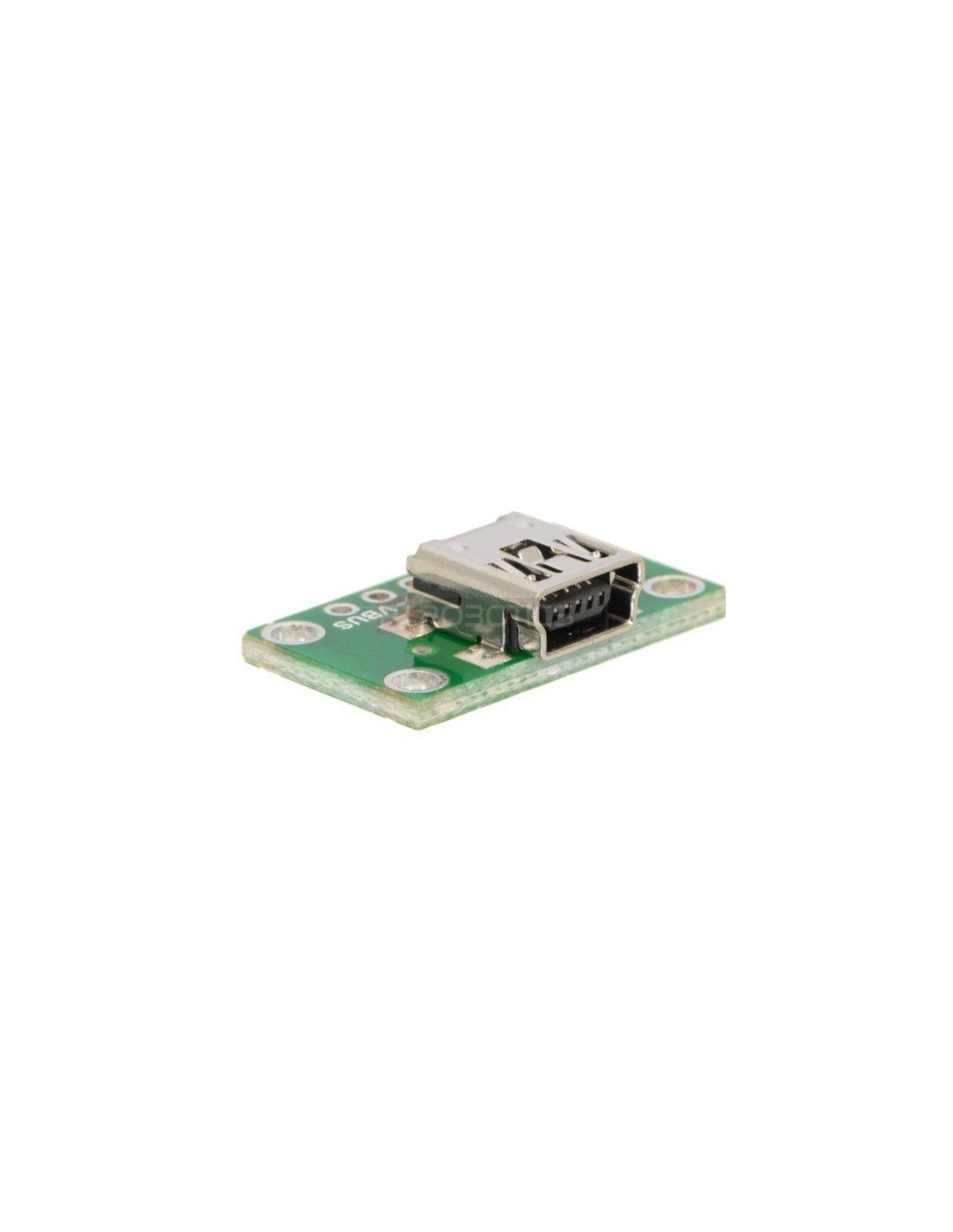
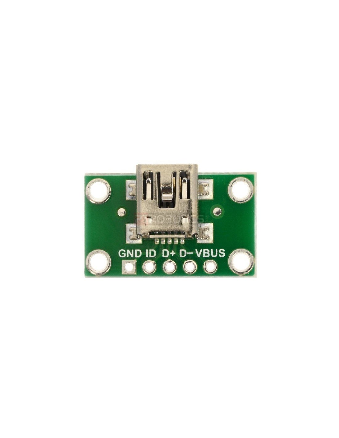
This simple board breaks out all five pins of a USB Mini-B connector to a 0.1″ pin spacing that is compatible with standard perfboards, solderless breadboards, and 0.1″ connectors.
 |
|
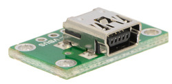
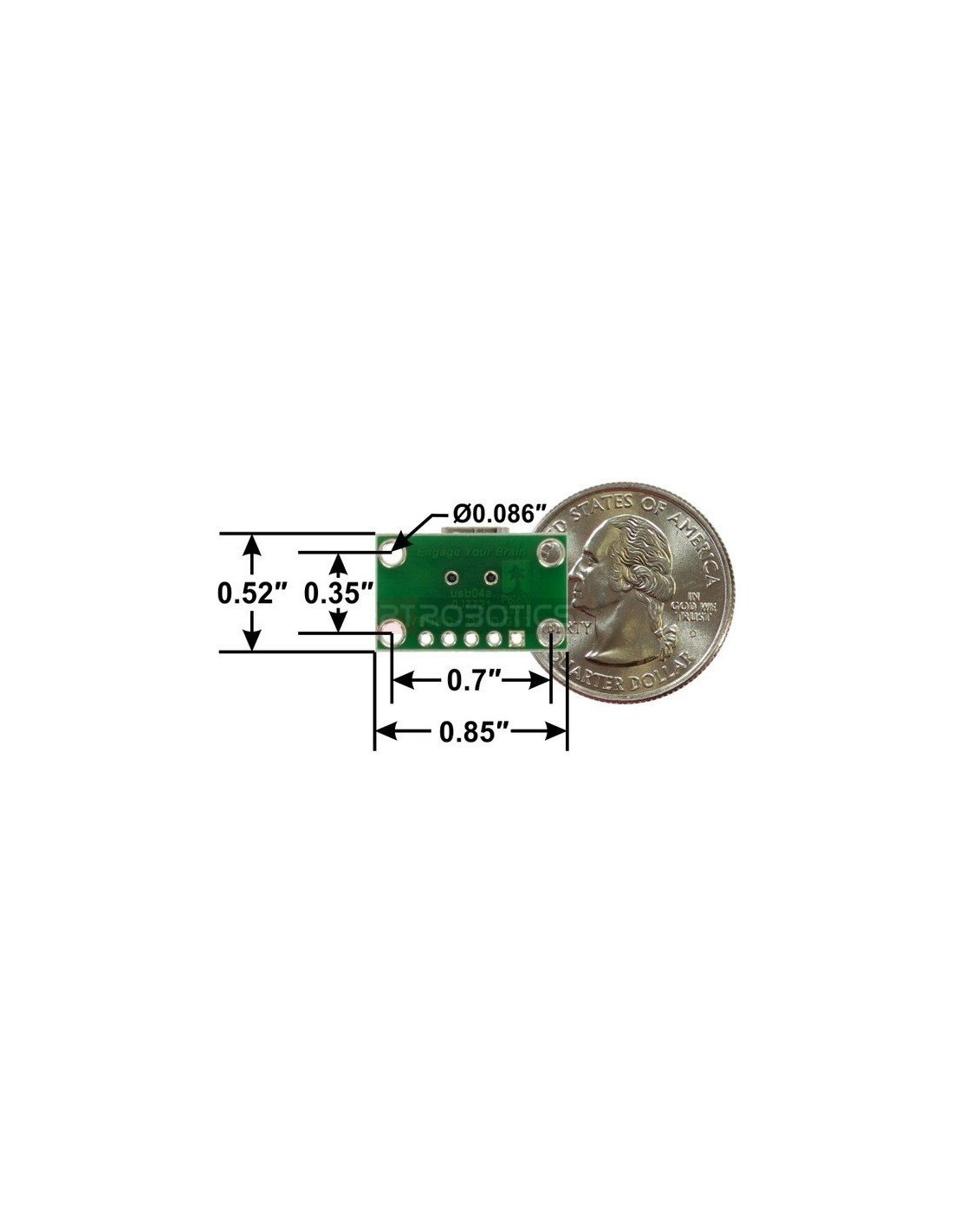
USB Mini-B connector breakout board, bottom view with dimensions. |
|---|
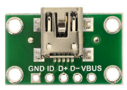
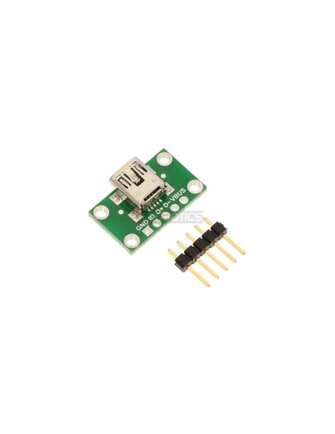
This board breaks out the VBUS, GND, D-, D+ and ID pins of a USB Mini-B connector. The VBUS and GND pins can be used to power your project from USB, while the D- and D+ pins give you access to the USB differential data signals. Each of these pins, along with the ID pin, are broken out into a 1×5 row of 0.1″-spaced pins on the board. The included 1×5 straight male header can be soldered to these pins to allow the board to be used with perfboards, solderless breadboards, and 0.1″ connectors.
This tiny unit measures only 0.52″ × 0.85″ (0.55″ × 0.85″ including its USB Mini-B connector) and has four 0.086″ diameter mounting holes for #2 or M2 screws.
|
|
We also carry a USB Micro-B connector breakout board, and we have two power muxes that double as USB Micro-B breakout boards: the FPF1320 carrier and the TPS2113A carrier. These latter two power multiplexers make it easy to have a device that can be powered from both USB and an external supply.
| Size: | 0.55″ × 0.85″ × 0.23″1 |
|---|---|
| Weight: | 1.5 g2 |


