Seu Carrinho
Não existem mais produtos no seu carrinho


This tiny board is an easy way to use Toshiba’s TB6612FNG dual motor driver, which can independently control two bidirectional DC motors or one bipolar stepper motor.
This tiny board is an easy way to use Toshiba’s TB6612FNG dual motor driver, which can independently control two bidirectional DC motors or one bipolar stepper motor. A recommended motor voltage of 4.5 V to 13.5 V and peak current output of 3 A per channel (1 A continuous) make this a great motor driver for low-power motors.
The TB6612FNG (308k pdf) is a great dual motor driver that is perfect for interfacing two small DC motors such as our micro metal gearmotors to a microcontroller, and it can also be used to control a single bipolar stepper motor. The MOSFET-based H-bridges are much more efficient than the BJT-based H-bridges used in older drivers such as theL298N and Sanyo’s LB1836M, which allows more current to be delivered to the motors and less to be drawn from the logic supply (the LB1836 still has the TB6612 beat for really low-voltage applications). Our little breakout board gives you direct access to all of the features of the TB6612FNG and adds power supply capacitors and reverse battery protection on the motor supply (note: there is no reverse protection on the Vcc connection).
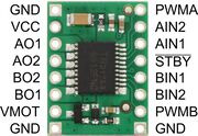 |
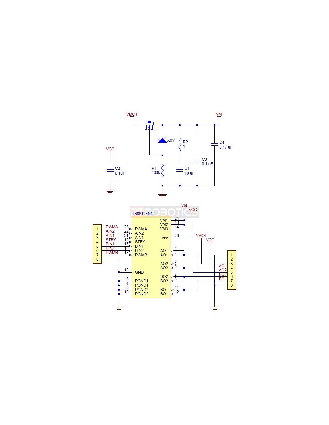
In a typical application, power connections are made on one side of the board and control connections are made on the other. All of the control inputs are internally pulled low. Each of the two motor channels has two direction control pins and a speed control pin that accepts a PWM input with a frequency of up to 100 kHz. TheSTBY pin must be driven high to take the driver out of standby mode.
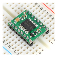 |
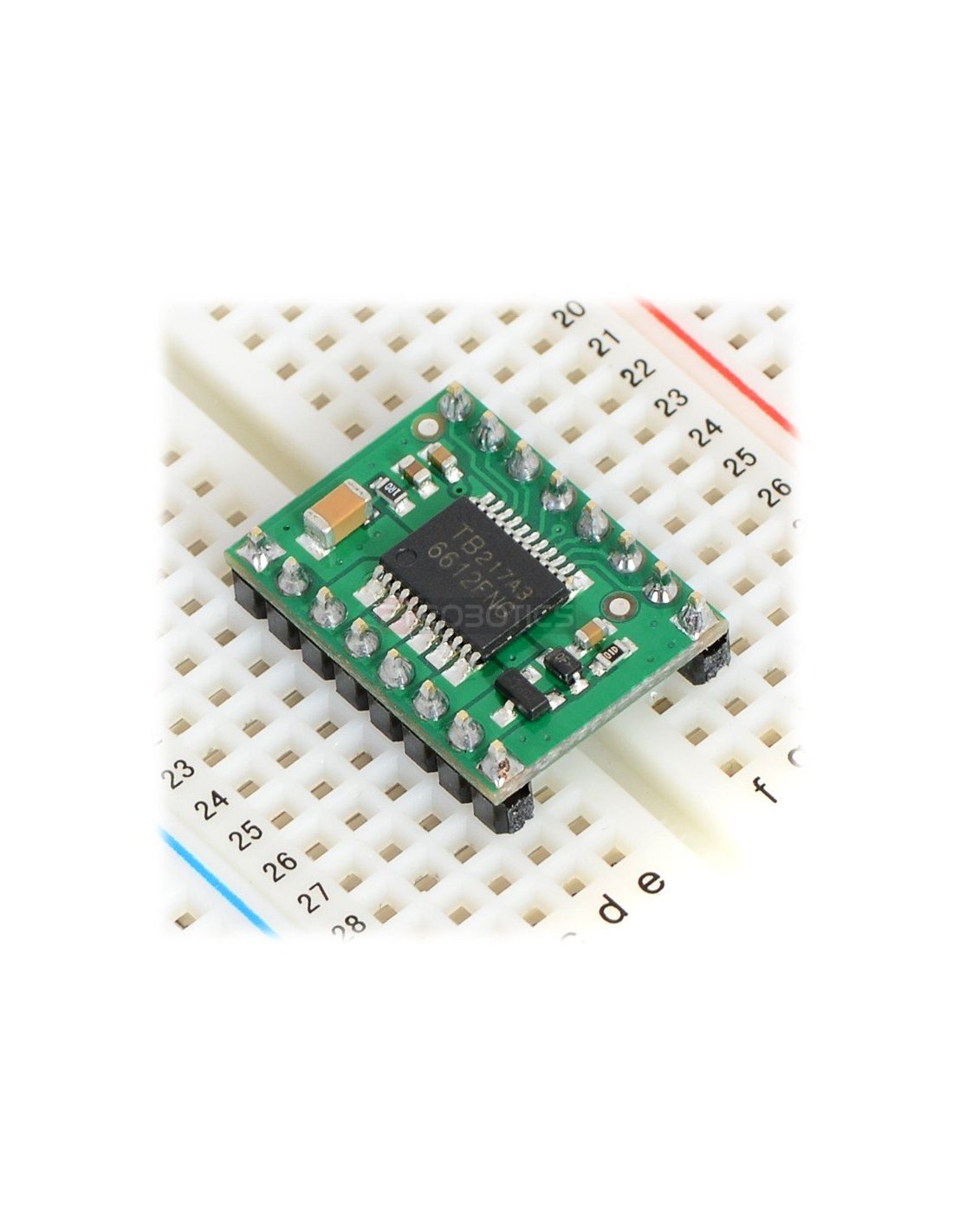
| TB6612FNG dual motor driver carrier on a breadboard. |
|---|
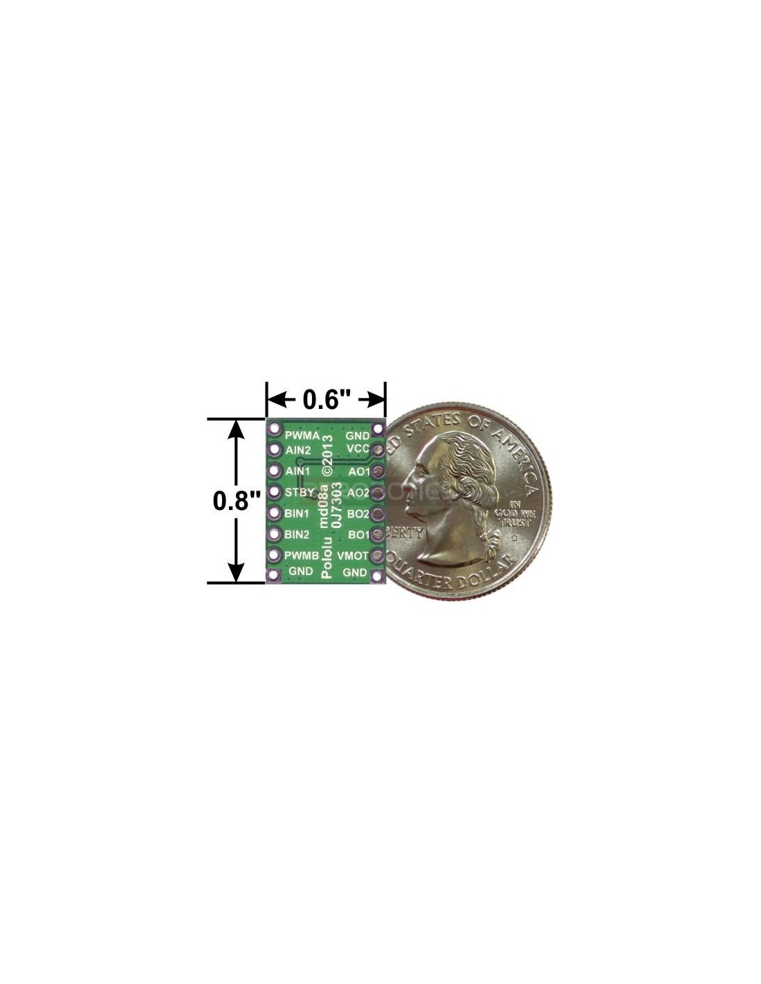
The distance between the header rows on the PCB is 0.1" smaller than a standard 0.6" DIP package, but the pin spacing allows it to conveniently fit in 0.1" breadboards and perfboards.
The TB6612 motor driver used on the carrier board has a peak current rating of 3 A per channel. The peak ratings are for quick transients (e.g. when a motor is first turned on), and the continuous rating of 1 A is dependent on various conditions, such as the ambient temperature. The actual current you can deliver will depend on how well you can keep the motor driver cool. The carrier’s printed circuit board is designed to draw heat out of the motor driver chip, but performance can be improved by adding a heat sink.
This product can get hot enough to burn you long before the chip overheats. Take care when handling this product and other components connected to it.
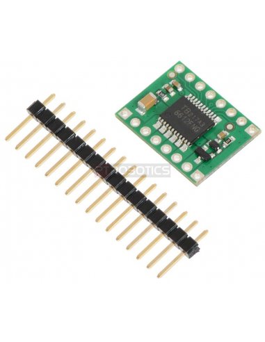
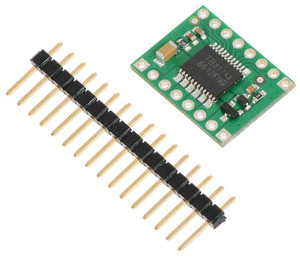
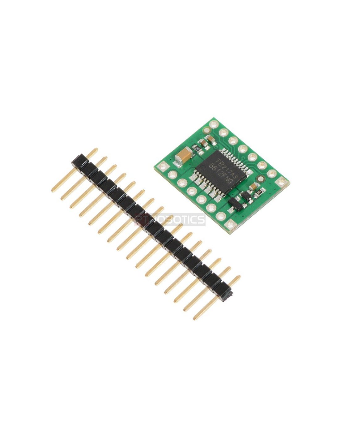
A 1×16-pin breakaway 0.1″ male header strip is included with the TB6612FNG motor driver carrier. This strip can optionally be soldered to the carrier board so that it can be used with perfboards, solderless breadboards, or 0.1″ female connectors. (The headers might ship as two 1×8 pieces or as a single 1×16 piece that can be broken in half.)
 |
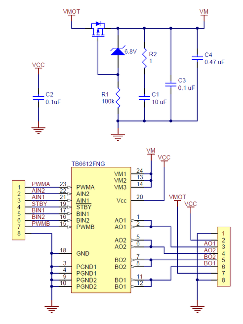 |
This schematic is also available as a downloadable pdf (156k pdf).
July 9, 2013 Update: We have changed this carrier board slightly by replacing the tall electrolytic capacitor with a much smaller ceramic capacitor. The two versions are functionally identical. The two versions are pictured below, with the left one showing the new version and the right showing the original version.


