Seu Carrinho
Não existem mais produtos no seu carrinho


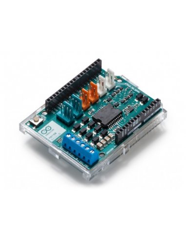
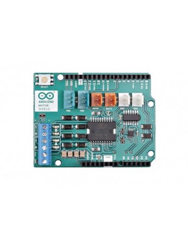


The Arduino Motor Shield is based on the L298 (datasheet), which is a dual full-bridge driver designed to drive inductive loads such as relays, solenoids, DC and stepping motors. It lets you drive two DC motors with your Arduino board, controlling the speed and direction of each one independently.
The Arduino Motor Shield is based on the L298 (datasheet), which is a dual full-bridge driver designed to drive inductive loads such as relays, solenoids, DC and stepping motors. It lets you drive two DC motors with your Arduino board, controlling the speed and direction of each one independently. You can also measure the current absorption of each motor, among other features. The shield is TinkerKit compatible, which means you can quickly create projects by plugging TinkerKit modules to the board.
| Operating Voltage | 5V to 12V |
| Motor controller | L298P, Drives 2 DC motors or 1 stepper motor |
| Max current | 2A per channel or 4A max (with external power supply) |
| Current sensing | 1.65V/A |
| Free running stop and brake function |
EAGLE files: arduino_MotorShield_Rev3-reference-design.zip
Schematic: arduino_MotorShield_Rev3-schematic.pdf
The Arduino Motor Shield must be powered only by an external power supply. Because the L298 IC mounted on the shield has two separate power units, one for the logic and one for the motor supply driver.The current draw for the motor supply is often than the USB can give.
External (non-USB) power can come either from an AC-to-DC adapter (wall-wart) or battery. The adapter can be connected by plugging a 2.1mm center-positive plug into the Arduino's board power jack on which the motor shield is mounted or by connecting the wires that lead the power supply to the Vin and GND screw terminals, taking care to respect the polarities.
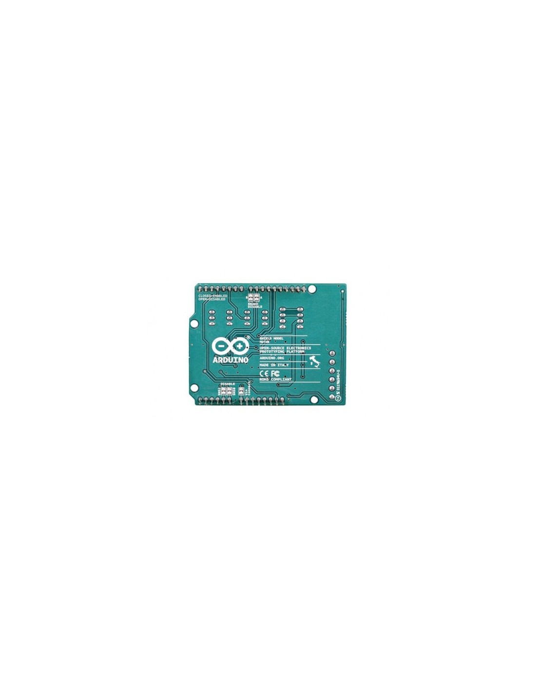
To avoid possible damage to the Arduino board on which the shield is mounted, we reccomend using an external power supply that provides a voltage between 7 and 12V. If your motor require more than 9V we recommend that you separate the power lines of the shield and the Arduino board on which the shield is mounted. This is possible by cutting the "Vin Connect" jumper placed on the back side of the shield. The absolute limit for the Vin at the screw terminals is 18V.
The power pins are as follows:
The shield can supply 2 amperes per channel, for a total of 4 amperes maximum.
This shield have two separate channels, called A and B, that each use 4 of the Arduino pins to drive or sense the motor. In total there are 8 pins in use on this shield. You can use each channel separately to drive two DC motors or combine them to drive one unipolar stepper motor.
The shield's pins, divided by channel are shown in the table below:
| Function | pins per Ch. A | pins per Ch. B |
| Direction | D12 | D13 |
| PWM | D3 | D11 |
| Brake | D9 | D8 |
| Current Sensing | A0 | A1 |
If you don't need the Brake and in the Current Sensing and you also need more pins for your application you can disable this features by cutting the respective jumpers on the back side of the shield.
The additional sockets on the shield are described as follow:
Brushed DC motor. You can drive two Brushed DC motors by connecting the two wires of each one in the (+) and (-) screw terminals for each channel A and B. In this way you can control its direction by setting HIGH or LOW the DIR A and DIR B pins, you can control the speed by varying the PWM A and PWM B duty cycle values. There are also the Brake A and Brake B pins that if setted in HIGH state they brakes the DC motor faster than when you power off the motor. You can know the current going through the DC motor by reading the SNS0 and SNS1 pins. On each channel will be a voltage proportional to the measured current, which can be read as a normal analog input, through the functions analogRead() on the analog input A0 and A1. For your convenience it is calibrated to be 3.3V when the channel is delivering its maximum possible current, that is 2A.
The maximum length and width of the Motor Shield PCB are 2.7 and 2.1 inches respectively. Four screw holes allow the board to be attached to a surface or case. Note that the distance between digital pins 7 and 8 is 160 mil (0.16"), not an even multiple of the 100 mil spacing of the other pins.


