Seu Carrinho
Não existem mais produtos no seu carrinho
 | HAT | Placas de Expansão Raspberry Pi")
 | HAT | Placas de Expansão Raspberry Pi")
 | HAT | Placas de Expansão Raspberry Pi")
 | HAT | Placas de Expansão Raspberry Pi")


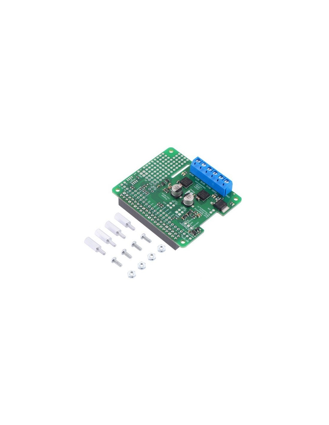
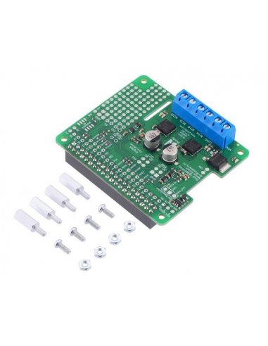
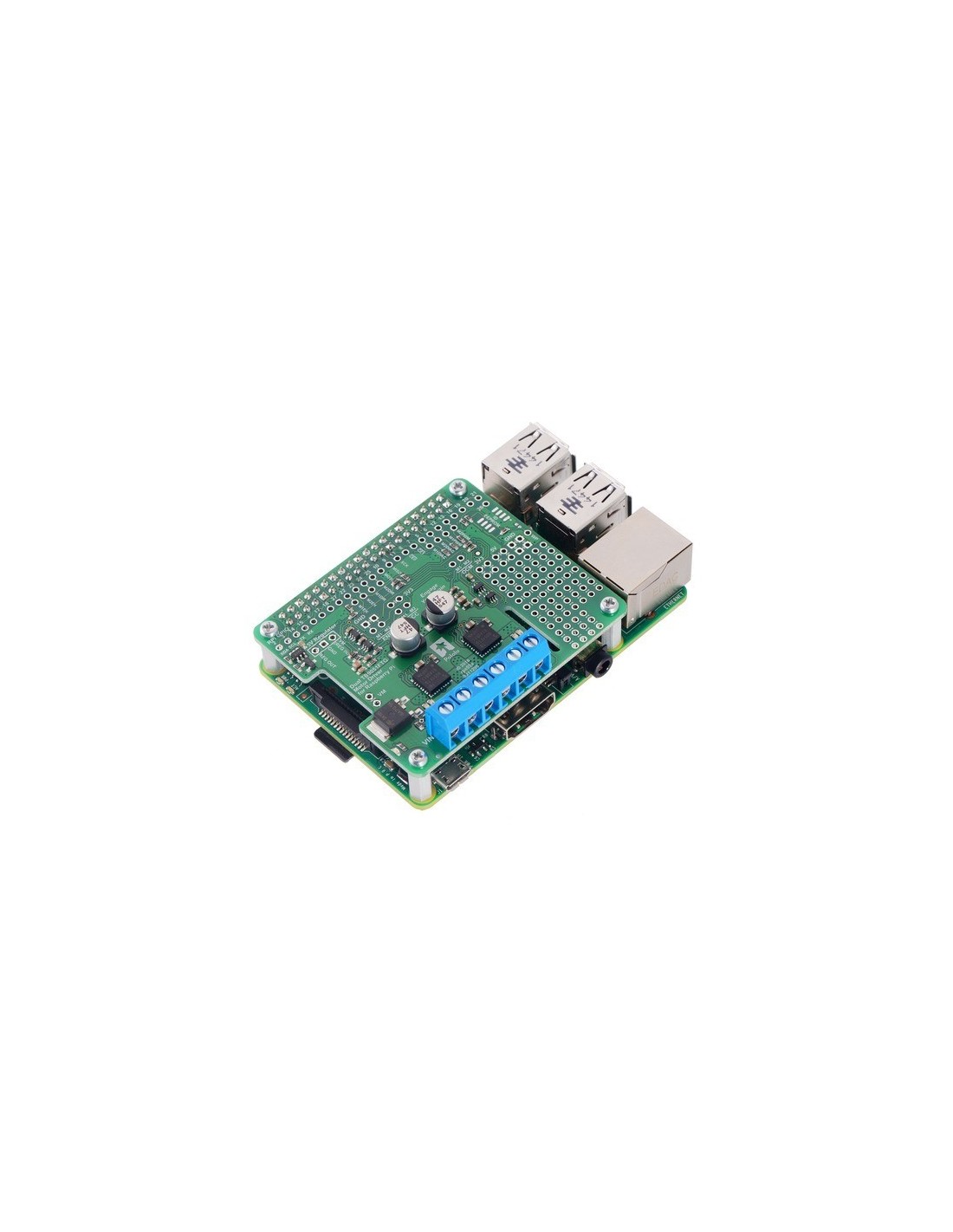
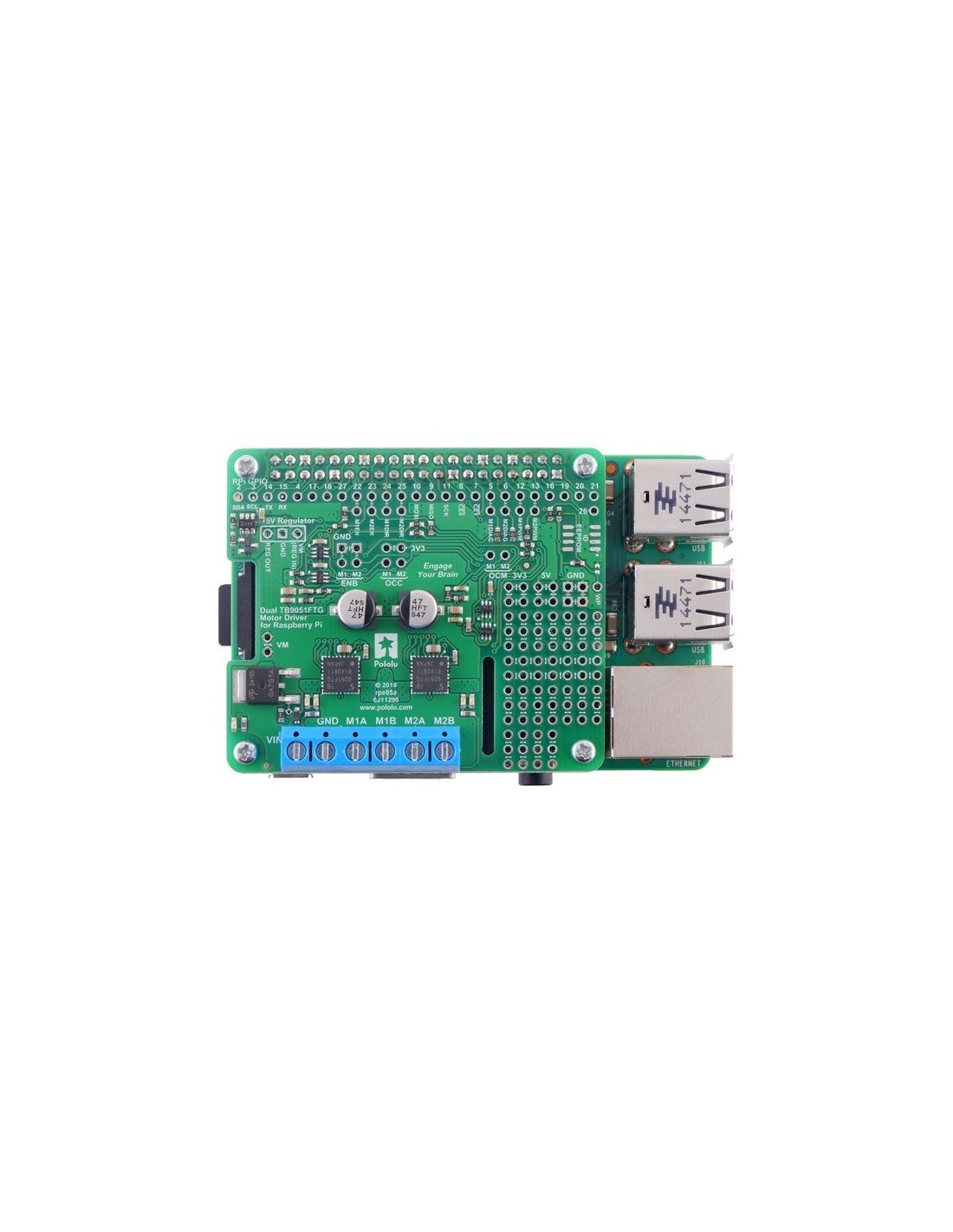
Shield Motor Driver Duplo TB9051FTG para Raspberry Pi (Assemblado)
Shield Motor Driver Duplo TB9051FTG para Raspberry Pi (Assemblado)
Esta board de expansão torna mais fácil o controlo de motores bidirecionais com o Raspeberry Pi (modelo B+ ou mais).
Descrição
Shield Motor Driver Duplo TB9051FTG para Raspberry Pi (Assemblado)
Informação do fabricante:
This motor driver expansion board and its corresponding Python library make it easy to control a pair of bidirectional, brushed DC motors with a compatible Raspberry Pi (Model B+ or newer), including the Pi 3 Model B+ and Model A+. The expansion board uses a pair of Toshiba TB9051FTG motor drivers, which operate from 4.5 to 28 V and can deliver a continuous 2.6 A per channel (up to 5 A per channel for a few seconds). Other features include a reverse battery protection circuit and logic gates that reduce the number of I/O pins required to control the driver ICs effectively. It is available either as a partial kit, with a female header and terminal blocks included but not soldered in, or fully assembled with these connectors soldered to the PCB.
The board’s default configuration uses six GPIO pins to control the motor drivers, making use of the Raspberry Pi’s hardware PWM outputs, and it uses two additional pins to read status outputs from the drivers. However, the pin mappings can be customized if the defaults are not convenient, and other control inputs and outputs of the TB9051FTG ICs are accessible on the board for more advanced applications.
The board matches the Raspberry Pi HAT (Hardware Attached on Top) mechanical specification, although it does not conform to the full HAT specifications due to the lack of an ID EEPROM. (A footprint for adding your own EEPROM is available for applications where one would be useful; pull-ups on SDA, SCL, and WP are provided.) It is not practical to use this expansion board with the original Raspberry Pi Model A or Model B due to differences in their pinout and form factor.
For controlling higher-power motors with a Raspberry Pi, consider our Dual G2 High-Power Motor Driver expansion boards, and for controlling lower-power motors with a smaller board, consider our DRV8835 dual motor driver or MAX14870 dual motor driver kits. We also have a similar dual TB9051FTG shield for Arduinos and Arduino-compatible boards and a basic single TB9051 carrier for those using a different controller or with tighter space constraints.
Features
Dual-channel H-bridge motor driver in the form factor of a Raspberry Pi expansion board
Wide operating voltage range: 4.5 V to 28 V
Output current: 2.6 A continuous (5 A peak) per motor
Automatic current chopping feature helps prevent overheating by gracefully reducing power rather than abruptly shutting down
PWM operation up to 20 kHz, which is ultrasonic and allows for quieter motor operation
Motor indicator LEDs show what the outputs are doing even when no motor is connected
Board can optionally power the Raspberry Pi base through added regulator like the D24V10F5 or D24V22F5 (not included)
Python library makes it easy to get started using this board as a motor driver expansion board
GPIO pin mappings can be customized if the default mappings are not convenient
Remaining motor driver pins are exposed for advanced use
Exposed solderable ground pads below the driver ICs on the bottom of the PCB
Reverse-voltage protection on motor supply
Robust drivers:
Transient operation (< 500 ms) up to 40 V
Under-voltage lockout and protection against over-current/short-circuit and over-temperature
Active-low error output indicates over-current, over-temperature, under-voltage, or VCC over-voltage condition
Prototyping space for easier/cleaner construction of custom circuits
Details:
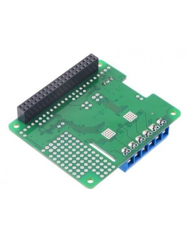
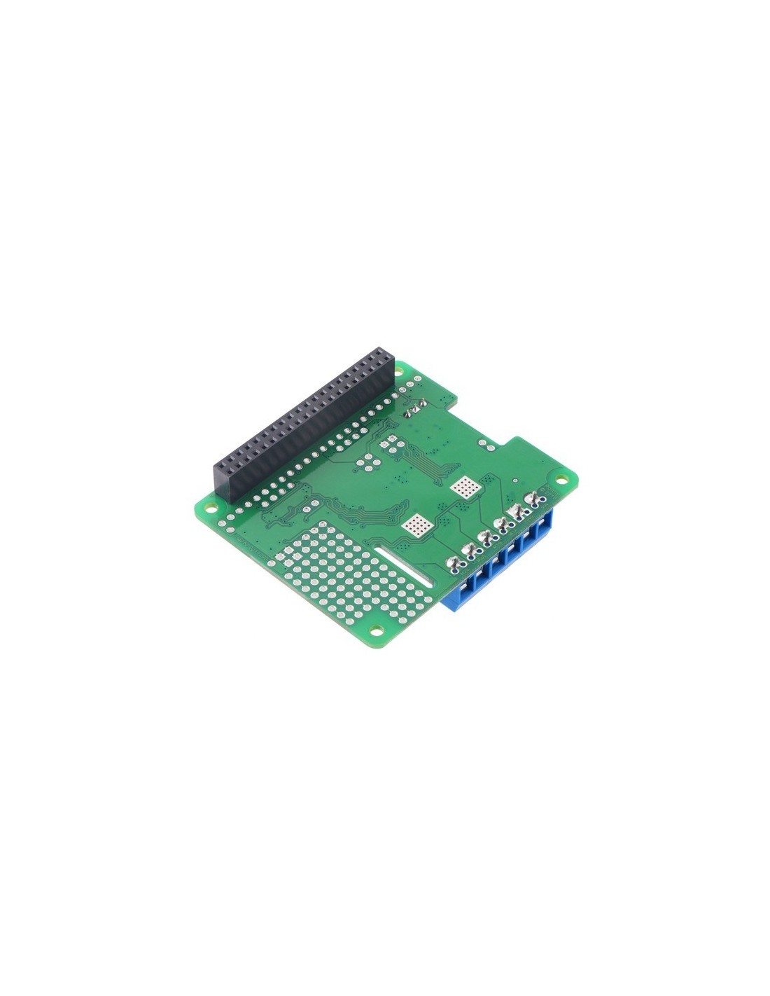
This version of the motor driver is fully assembled, with a 2×20-pin 0.1″ female header (for connecting to the Raspberry Pi’s 40-pin GPIO header) and a six-pin strip of 5 mm terminal blocks (for motor and power connections) soldered in. (See item #2761 for a kit version with connectors included but not soldered in.)
The motor driver ships with a set of four M2.5 standoffs (11 mm length), screws, and nuts that can be used to secure the board to the Raspberry Pi at the proper height for the GPIO connector. If you decide not to use the standoffs, be careful not to allow the motor and power connections to short against the Raspberry Pi’s HDMI connector.
Shorting blocks and 0.1″ male headers (not included) can be used to make some of the more advanced optional modifications to the board, such as remapping the control pins.
A Raspberry Pi is not included.
Using the motor driver board
This section explains how to use the dual TB9051FTG motor driver add-on board and provides some basic information about the motor driver pins to help get you started. However, we strongly encourage you to consult the TB9051FTG datasheet (2MB pdf) for detailed pin descriptions, truth tables, and electrical characteristics. This expansion board is essentially a breakout board for two TB9051FTG motor driver ICs with additional logic circuitry to simplify the motor control, so the datasheet is your best resource for answering questions not covered here.
In the board’s default state, the motor driver outputs and the Raspberry Pi are powered separately, though they share a common ground. The board’s 3.3 V and 5 V logic supplies are provided by the Raspberry Pi. When used this way, the Raspberry Pi must be powered via its USB Micro-B receptacle, and the motor driver board must be supplied with 4.5 V to 28 V through its large VIN and GND pads. However, the motor driver board provides a set of three through-holes where you can conveniently connect an appropriate voltage regulator, allowing the motor supply to also power the Raspberry Pi (see the Powering the Raspberry Pi from the motor driver board section below).
A reverse-voltage protection circuit helps prevent damage to the board in case the motor power supply is connected backward. The reverse-protected input voltage can be accessed for use in other circuits through the two pins labeled VM on the left side of the board.
The board includes logic gates that enable drive/brake operation of the TB9051FTG drivers with only two control pins per motor (PWM and direction). As drive/brake operation usually provides a more linear relationship between PWM duty cycle and motor speed than drive/coast operation, we generally recommend using drive/brake operation when possible.
Dual TB9051FTG Motor Driver for Raspberry Pi controlling a pair of motors.
Powering the Raspberry Pi from the motor driver board
On the left side of the expansion board is a set of three pins surrounded by a box labeled “5V Regulator”. The “VM (REG IN)” pin provides access to the driver board’s motor supply voltage after reverse-voltage protection, while the “REG OUT” pin is connected to the Raspberry Pi’s 5V power rail through an ideal diode circuit. If a suitable voltage regulator is connected to these three pins, it can generate 5 V to power the Raspberry Pi from the board’s motor supply voltage.
We suggest using our D24V10F5 or D24V22F5, which work at input voltages exceeding the 28 V maximum of the TB9051FTG (see below for details on which to choose), and can supply up to 500 mA or 1 A of current, respectively, to the Raspberry Pi.
When adding a voltage regulator to the motor driver board, take care to orient it correctly: note that the motor driver board’s “VM (REG IN)” pin should connect to the regulator’s VIN pin, while the regulator’s VOUT pin should connect to the motor driver board’s REG OUT pin.
Your motor power supply must be an acceptable voltage for both the regulator and the TB9051FTG driver ICs. The ideal diode circuit makes it safe to have a different power supply connected to the Raspberry Pi through its USB Micro-B receptacle while the motor driver add-on and regulator are connected and powered.
The regulator should be able to handle the power requirements of the Raspberry Pi. The Model B+ typically uses a few hundred milliamps at 5 V, although its current draw can exceed 1 A if it is also supplying power to USB devices and other peripherals. While a linear regulator like a 7805 might fit in the regulator mounting location, it could generate excessive heat or shut down at higher input voltages and output currents. We recommend using a switching regulator like the ones mentioned above.
The D24V22F5 can supply up to 2.5 A and is more suitable for higher-performance Raspberry Pi models (like the Pi 3 B+), especially with demanding workloads or when powering many peripherals. Because of its larger size, it must be connected through longer headers or wires to avoid interference with the terminal blocks.
Detalhes do produtos
Toque para aumentar