Seu Carrinho
Não existem mais produtos no seu carrinho


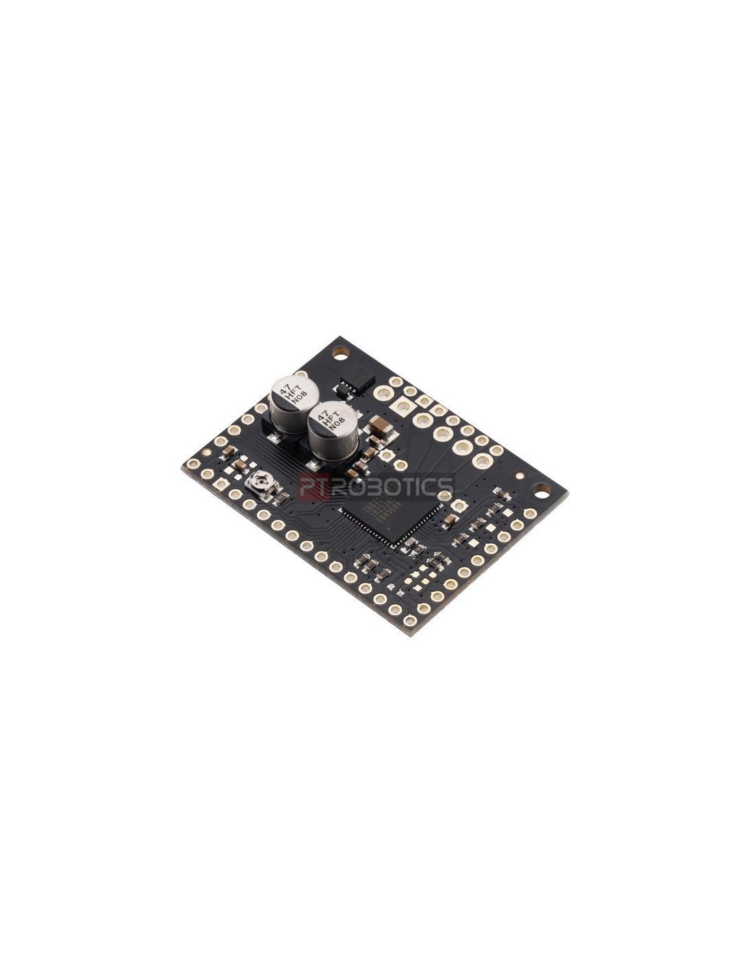
Driver para Motor de Passo TB67S128FTG
Informação do fabricante:
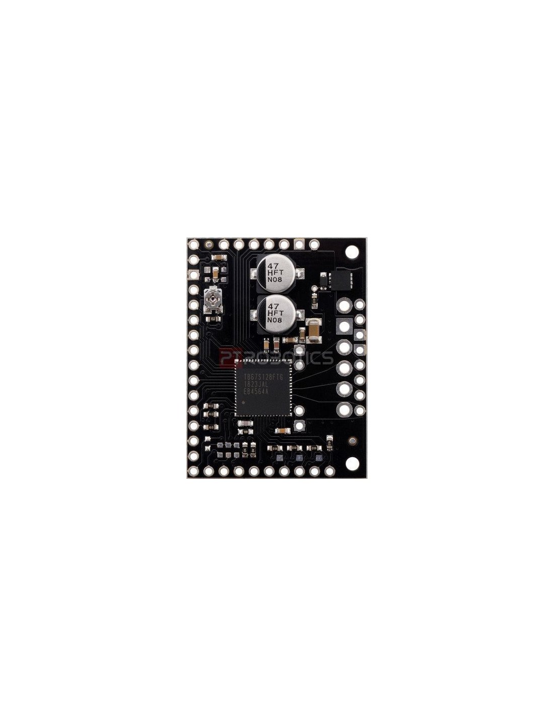
This breakout board makes it easy to use Toshiba’s TB67S128FTG microstepping bipolar stepper motor driver, which features adjustable current limiting and microstepping down to 1/128-step. In addition, it has the ability to dynamically select an optimal decay mode by monitoring the actual motor current, and it can automatically reduce the driving current below the full amount when the motor is lightly loaded to minimize power consumption and heat generation. The driver has a wide operating voltage range of 6.5 V to 44 V and can deliver approximately 2.1 A per phase continuously without a heat sink or forced air flow (up to 5 A peak). It features built-in protection against under-voltage, over-current, and over-temperature conditions; our carrier board also adds reverse-voltage protection (up to 40 V).
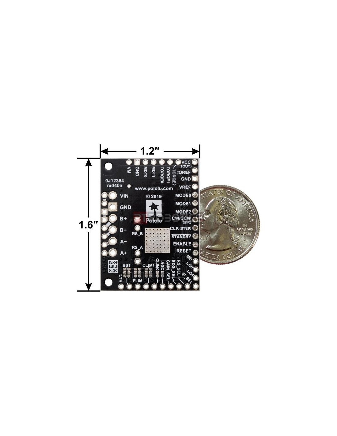
This product is a carrier board or breakout board for Toshiba’s TB67S128FTG stepper motor driver; we therefore recommend careful reading of the TB67S128FTG datasheet (2MB pdf) before using this product. This stepper motor driver offers microstep resolutions down to 1/128 of a step, and it lets you control one bipolar stepper motor at up to approximately 2.1 A per phase continuously (5 A peak) without a heat sink or forced air flow (see the Power Dissipation Considerations section below for more information.) The board breaks out every control pin and output of the TB67S128FTG, making all of the driver’s features available to the user.
Here are some of the board’s key features:
clock mode for simple step and direction control
serial mode for controlling the driver’s many features through a serial interface (this mode also allows for serial control of the current limit)
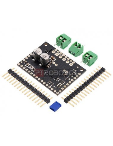
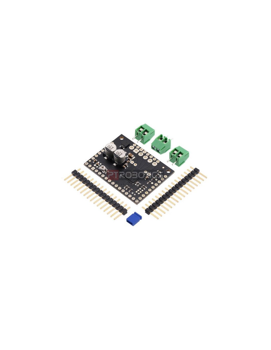
Included hardware:
This product ships with all surface-mount components installed as shown in the product picture. However, soldering is required for assembly of the included through-hole parts. The following through-hole parts are included:
The 0.1″ male headers can be broken or cut into smaller pieces as desired and soldered into the smaller through-holes. These headers are compatible with solderless breadboards, 0.1″ female connectors, and our premium and pre-crimped jumper wires. The terminal blocks can be soldered into the larger holes to allow for convenient temporary connections of unterminated power and motor wires (see our short video on terminal block installation). You can also solder your motor leads and other connections directly to the board for the most compact installation.
For more detailed information, please check this link.

